Flux-Surface Geometry
Clebsch coordinates
GYRO/CGYRO/NEO use a right-handed (positively-oriented), field-aligned coordinate system \((r,\theta,\alpha)\) and the Clebsch field representation [KK58]
where \(\psi\) is the poloidal flux divided by \(2\pi\) and
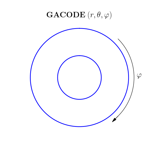
is the Clebsch angle. Here, \(\varphi\) is the toroidal angle, oriented as shown in the figure below, and \(\theta\) is the poloidal angle which increases as one moves counterclockwise along the flux-surface (shown in blue). In these coordinates, the Jacobian is
Since the coordinates \((\psi,\theta,\alpha)\) and \((\psi,\theta,\varphi)\) form right-handed systems, the Jacobian \(\jp\) is positive-definite. In the latter coordinates, the magnetic field becomes
Using the definition of the safety factor, \(q(\psi)\), we may deduce
For concreteness, we choose the following boundary conditions for \(\nu\):
By writing \(\B\) in the standard form
we can derive the following integral for \(\nu\):
In the case of concentric (unshifted) circular flux surfaces, one will obtain the approximate result \(\nu(\psi,\theta) \sim -q(\psi)\theta\). Finally, we remark that the coordinate systems \((R,Z,\varphi)\) and \((r,\theta,\varphi)\) are positively oriented.
Bounding-box method
In the MXH parameterization [ACB21], we use the bounding-box method to define
minor radius \(r\)
major radius \(R_0\)
elongation \(\kappa\)
elevation \(Z_0\)
via the flux-surface contour extrema
Effective field
The effective field strength, \(B_{\rm {unit}}\), is defined as
where \(\chi _{t}\) is the toroidal flux divided by \(2\pi\). This gives the roughly equivalent field that would be obtained if the flux surface was deformed to a circle.
Equilibria
GYRO/CGYRO/NEO can be run using circular equilibrium or shaped Grad-Shafranov equilibrium.
(1) Circular equilibrium
The flux surfaces, which are not local G-S equilibria, have the form:
\[\begin{split}R(r,\theta) &= R_0 + r \cos \theta \\ Z(r,\theta) &= r \sin \theta \\\end{split}\]
where \(\nu(r,\theta) = -q(r) \theta\).
CGYRO: EQUILIBRIUM_MODEL = 1
NEO: EQUILIBRIUM_MODEL = 0
(2) Shaped Grad-Shafranov equilibrium
The flux surfaces, which are local G-S equilibria, have the new MXH3 parameterization [ACB21]:
where \(\nu(r,\theta)\) is computed numerically. The harmonic angle \(\theta_R\) is
\(c_n\) are anti-symmetric moments and \(s_n\) are symmetric moments.
CGYRO: EQUILIBRIUM_MODEL = 2
NEO: EQUILIBRIUM_MODEL = 2 or PROFILE_EQUILIBRIUM_MODEL = 1
For experimental profiles, shape parameters are auto-generated from profile data.
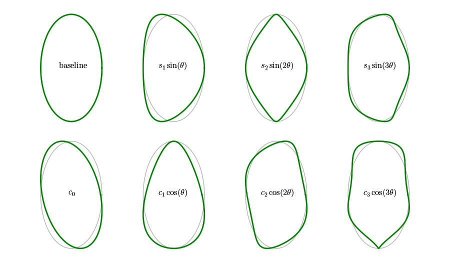
Table of geometry parameters
Symbol |
input.cgyro parameter |
input.neo parameter |
meaning |
|---|---|---|---|
\(r/a\) |
minor radius |
||
\(R_0(r)/a\) |
major radius |
||
\(\partial R_0/\partial r\) |
Shafranov shift |
||
\(Z_0(r)/a\) |
elevation |
||
\(\partial Z_0/\partial r\) |
elevation shift |
||
\(q\) |
safety factor |
||
\(s\) |
shear |
||
\(\kappa\) |
elongation |
||
\(s_\kappa\) |
|||
\(\delta = \sin s_1\) |
triangularity |
||
\(s_\delta\) |
|||
\(\zeta = -s_2\) |
squareness |
||
\(s_\zeta\) |
|||
\(c_0\) |
tilt |
||
\(s_{c_0}\) |
|||
\(c_1\) |
ovality |
||
\(s_{c_1}\) |
|||
\(c_2\) |
|||
\(s_{c_2}\) |
|||
\(c_3\) |
|||
\(s_{c_3}\) |
|||
\(s_3\) |
|||
\(s_{s_3}\) |
|||
\(\beta_e\) |
NA |
||
\(\beta_*\) scaling |
|||
BTCCW |
|||
IPCCW |
For further information about geometry and normalization conventions, consult the GYRO Technical Guide [CB10].
Magnetic field orientation
GACODE uses a right-handed (positively-oriented), field-aligned coordinate system \((r,\theta,\varphi)\), whereas DIII-D uses a (positively-oriented) cylindrical system \((R,\phi,Z)\). Looking down on the tokamak from above, the orientation of the GACODE toroidal angle is clockwise, whereas the DIII-D toroidal angle is counter-clockwise:

In reality, quantities like the safety factor and poloidal flux have definite signs. Historically, these signs have been suppressed or neglected in both theory and modeling. For proper treatment of momentum transport, however, these signs must be retained. We can infer typically neglected signs by knowing IPCCW and BTCCW. For example:
sign(\(B_{\rm tor}\)) = -BTCCW
sign(\(B_{\rm pol}\)) = -IPCCW
sign(\(\psi_{\rm pol}\)) = -IPCCW
sign(\(q\)) = IPCCW \(\times\) BTCCW
The standard configuration in DIII-D is shown below.
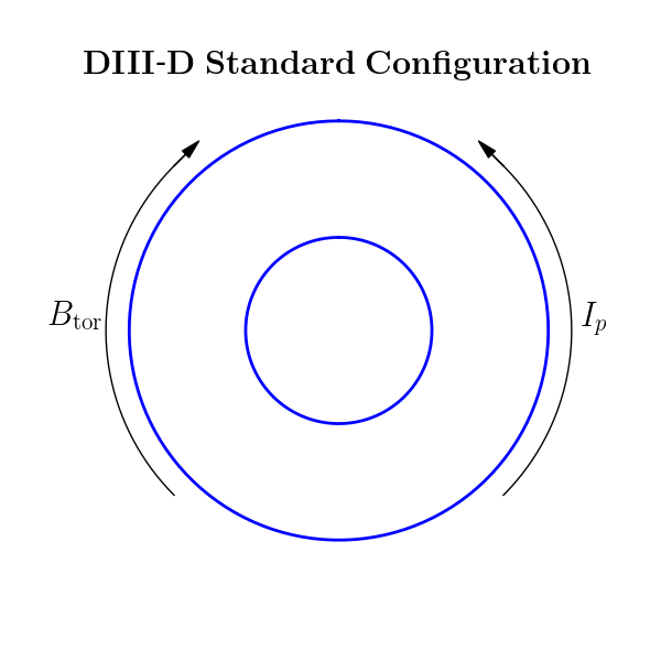
This corresponds to IPCCW = 1 and BTCCW =-1. Thus, in GACODE coordinates, we expect:
sign(\(B_{\rm tor}\)) = 1
sign(\(B_{\rm pol}\)) = -1
sign(\(\psi_{\rm pol}\)) = -1
sign(\(q\)) = -1
In other words, the safety factor and poloidal flux are negative in the typical case. This will be reflected in a properly-constructed input.gacode file.
Toroidal and poloidal flux
We can start from the general forms of the toroidal and poloidal fluxes [DhaeseleerHCS91]
Explicitly inserting the field-aligned coordinate system of the previous section, and differentiating these with respect to \(\psi\), gives
Thus, \(\psi\) is the poloidal flux divided by \(2\pi\). For this reason, it is useful to also define the toroidal flux divided by \(2\pi\):
According to these conventions,